Tutorial: Post-production in 3ds Max and Photoshop
Master core post-production skills to improve your interior renders as Jamie Cardoso explores how to generate render elements in 3ds Max, composite them in Photoshop and apply Adjustment Layers and effects.
REQUIRES: 3ds Max 2010+, Photoshop CS3+, V-Ray 1.50+ (optional)
DIFFICULTY: Elementary
TIME TAKEN: 2 hours
PROJECT FILES: Click here to download the files for the tutorial
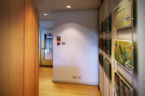
In this tutorial, we will explore the process of post-producing the interior image above, using the files from a real commercial job for Capital One. We will begin by exporting render elements from the scene in 3ds Max, then use Photoshop to composite these elements to form the final image.
It’s worth noting that the client specifically asked me to use this camera view for the purposes of the tutorial, since the project is very sensitive. The original image had a more conventional composition. However, this doesn’t affect the rendering or post-production techniques we will be exploring.
Generating the Z Depth pass
Before jumping into Photoshop, we will look at how to generate the files we need to create the composite in 3ds Max. I can’t release the original 3ds Max scene file publicly, but you may still find the information useful in your own projects. If you want to dive straight into post-production, just click here to skip ahead.
As well as the main render, I generated a number of standard render elements. I used V-Ray for the rendering work, but I will also explore briefly how to generate the same elements in 3ds Max’s built-in mental ray renderer.
The first of these is Z Depth. This is a greyscale image that represents the distance of each point in the scene from the render camera: light areas are nearer the camera, and dark ones are further away. This information will be crucial to creating a depth-of-field effect in post.
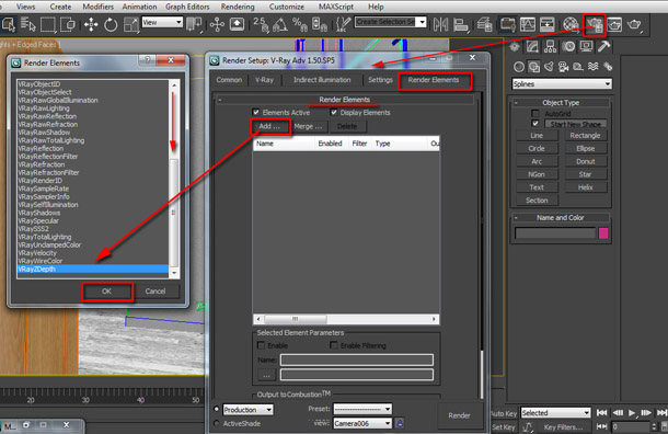
Open the Render Setup dialog by pressing the [F10] key or by clicking on its icon in the main toolbar (ringed in the image above). In the Render Elements tab, click the Add button to open its dialog. If you’re rendering in V-Ray, select VRayZDepth from the list.
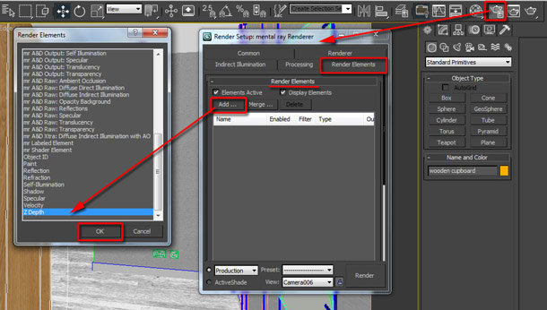
Alternatively, if you’re using mental ray, select Z Depth instead.
The Z Depth information works best in post when there is a clear contrast between the dark and bright areas. You can ensure that this is the case by carrying out test renders using different Z depth settings. For most eye-level camera shots, it’s usual to start with the minimum depth set to 0.0 metres and the maximum depth set to a low value, then gradually increase this value if necessary. We’ll look at how to do this in a minute.
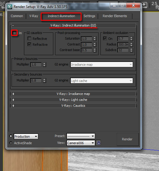
But before you begin tweaking, it’s best to make your test renders as fast as possible. First, you need to reduce the image sampling values and disable GI and/or Final Gather. The image above shows how to do this in V-Ray.
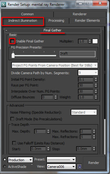
And this image shows how to do so in mental ray.
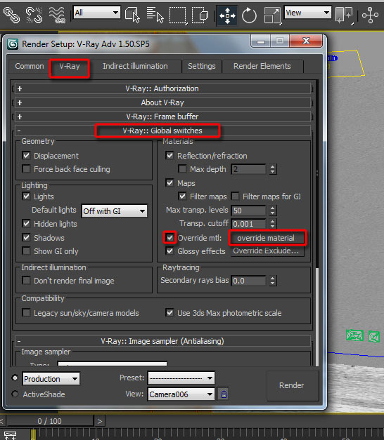
It’s also advisable to use a simple override material, as shown above in V-Ray.
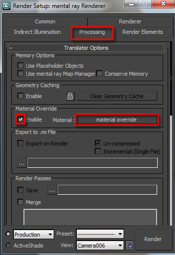
And here in mental ray. Finally, you should minimise the size of the test renders you are generating. In the Render Setup dialog, switch to the Common tab and open the Common Parameters rollout. In the Output Size group, set Width and Height to 500 x 322 pixels.
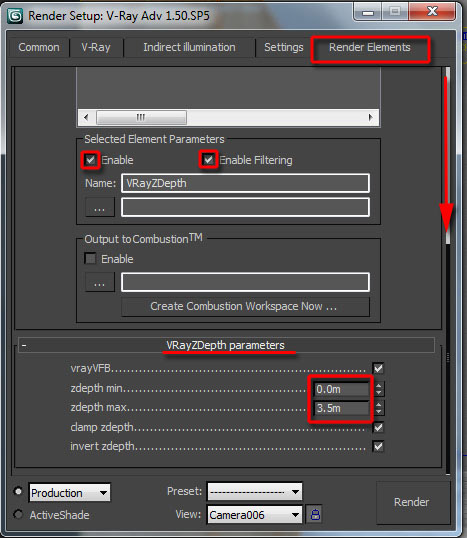
Back in the Render Elements tab, scroll down to the VRayZDepth parameters rollout and begin adjusting the zdepth min and zdepth max values. The figures that worked best for this scene were 0.0m and 3.5m. In the rollout above, make sure Enable and Enable Filtering are checked.
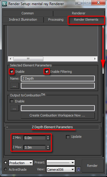
If you’re using mental ray, you need the ZDepth Element Parameters rollout and the Z Min and Z Max values. Again, make sure Enable and Enable Filtering are checked.
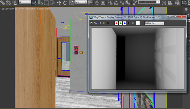
The Z Depth pass you generate should look something like this.
It’s worth noting that, by default, 3ds Max automatically sets the file path of the render elements to coincide with the one chosen in the Render Output group of the Common Parameters rollout. If you need to change this, go to the Selected Element Parameters group (where you checked the Enable and Enable Filtering boxes earlier) and click on the toggle (the … icon) to set the file path.
Generating the ambient occlusion pass
The next render element we will generate is ambient occlusion. The AO pass is also a greyscale image, this time indicating the degree to which surrounding surfaces block bounced light from reaching each point in the scene. It is often used to give the image more depth.
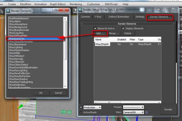
To add this render element in V-Ray, click the Add button in the Render Elements rollout again and choose the VRayExtraTex element from the Render Elements dialog.
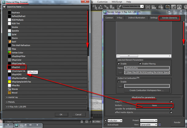
Once the element is added, scroll down to the VRayExtraTex parameters rollout and click on the texture toggle. In the Material/Map Browser dialog, choose the VRayDirt shader by double-clicking it. Depending on which version of 3ds Max you are using, you will find the shader in either the Standard rollout or the VRay… rollout.
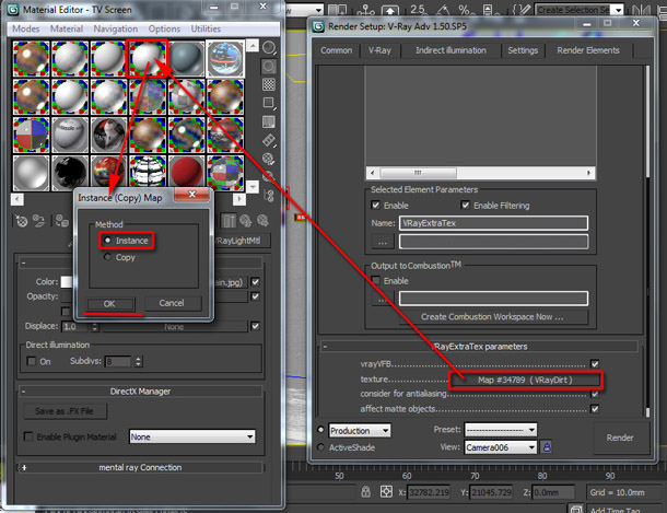
Once loaded, tweak the default parameters to make its effect more/less visible in the render. To view and edit the VRayDirt shader, simply drag its toggle from the Render Elements tab, and drop it onto the Material Editor. A dialog should appear. Choose the Instance copy method then OK to close the dialog.
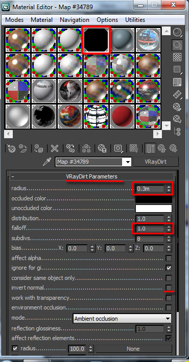
In real projects, with realistic dimensions, the following values often work very well: radius= 0.3m, falloff= 1.0. Feel free to try different values if you want! In some cases, you may also want to check the invert normal setting to generate shadows on corners of objects pointing outwards.
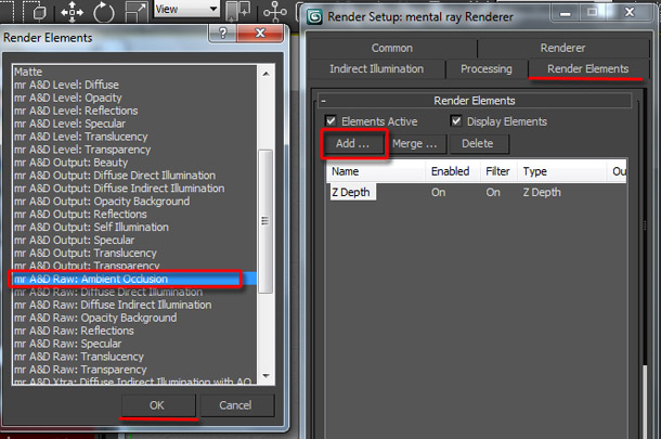
In mental ray, to add the ambient occlusion pass, click the Add button and choose mr A&D Raw: Ambient Occlusion element from the Render Elements dialog list.
Adding the object ID pass
The next element to add is the object ID pass. This renders each object in the scene a different flat colour: a crucial time-saver when selecting specific areas of the image to edit in post. The corresponding render element is called Object ID in mental ray and VRayWireColor or MultiMatteElement in VRay.
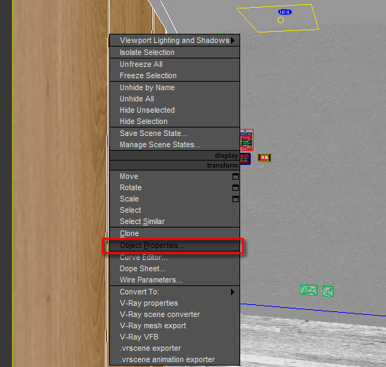
In order for these elements to work properly, it is necessary to assign ID numbers to the relevant objects in the scene. To do so, simply select any relevant object in the scene and right-click to bring up the quad menu. Choose the Object Properties option to open the dialog.
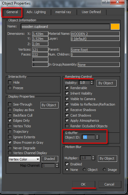
In the General tab, under the Rendering Control group, type a number in the G-Buffer Object ID field, and close the dialog box. Repeat this process for each object you want to assign an ID number to. Assign a different number to each.
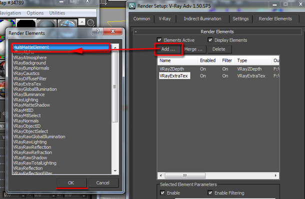
If you’re using V-Ray, add a MultiMatteElement in the same way as you added the previous render elements. You could also try VrayWireColor, as I have done in this tutorial, which uses the objects’ viewport colours to generate the ID colour.
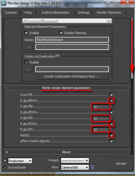
The MultiMatteElement uses true RGB values which are easier and more accurate to select in post; but the element itself is less intuitive to use. Each number displayed in its Matte render elements parameters rollout corresponds to a default object ID number, and is chosen randomly. You can change them to match the actual ID numbers you have assigned to objects in the scene.
By default, only G gbufID is enabled. This renders the corresponding object in the scene in green. You can enable R gbufID and B gbufID to render other objects in red or blue.
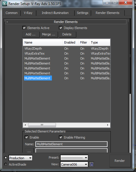
However, since most real scenes will require you to render more than three objects, you can generate more than one MultiMatteElement pass from the Render Elements list to render four or more separate Object IDs. (Note: when you are creating additional MultiMatteElement passes, make sure you rename them, in order to prevent existing passes from being overridden.)
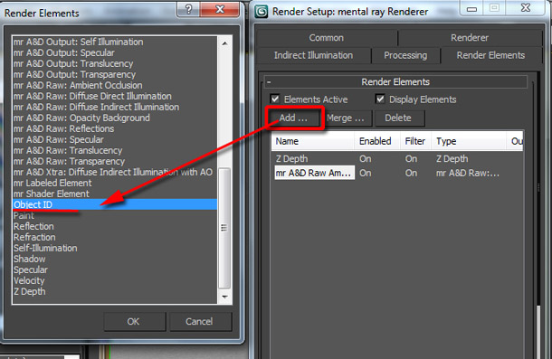
In mental ray, just add the Object ID or Material ID element.
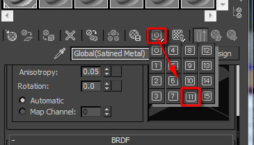
When adding render elements with Material ID information, you also need to change the default Material ID number for each Material Editor slot. To do so, click and hold down the ‘0‘ button to choose any of the 15 values available for each slot.
Adding the other render elements
The additional three render elements needed for this scene are reflections, refractions and the specular pass. You can generate these in the same way as before. In V-Ray, the relevant elements are VrayRawReflection, VRayRawRefraction and VRaySpecular; in mental ray, mr A&D Raw: Reflections, Refraction and mr A&D Raw: Specular. There are some cases where these elements won’t contribute much in post, but they usually help invigorate the image or help control specific post effects .
Preparing to render
Once the render elements are set up, it’s almost time to render the scene. But before you do so, there are a few final settings to adjust. (You may also want to generate and save the Final Gather maps for mental ray or the V-Ray irradiance map and light cache to speed up the renders, but we won’t be looking at how to do so here.)
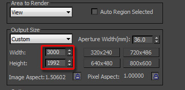
First, set Width and Height in the Output Size group to the dimensions in pixels you want the final render to be. The values above are usually sufficient for print use.
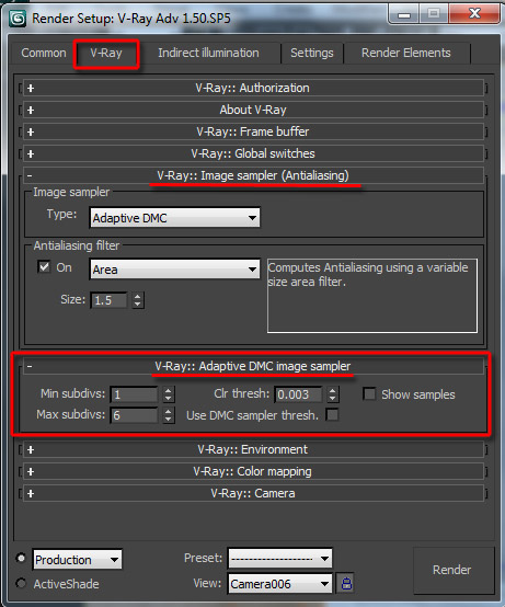
Next, increase the sampling settings to values similar to those shown above if you’re using V-Ray…
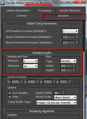
…or those shown above if you’re using mental ray. When this is done, render the scene.
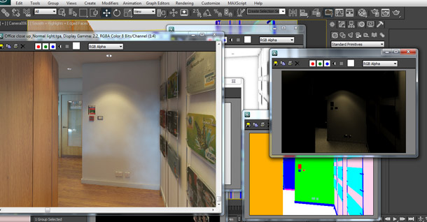
After the render is done, all the elements should appear in succession, and in separate frame buffers.
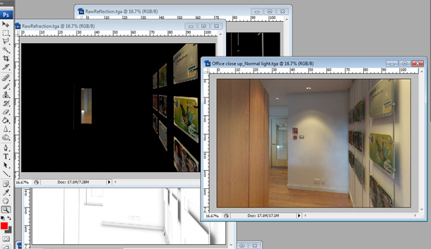
Once everything has rendered, open all the files in Photoshop in begin post-production. You can find passes I’ve already rendered for you in the download accompanying the tutorial.
Some of the elements may ultimately prove irrelevant to the finished composite – so we won’t be using all of the files from the download in the steps below – but as a matter of good practice, it’s worth rendering anything likely to prove useful
Beginning the Photoshop work
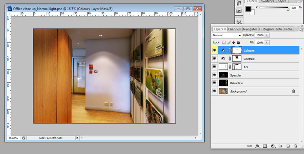
It’s time to begin the post work. If you get stuck at any point, you can open my completed PSD files to check how they are structured. Composite.psd shows the early adjustments, while Depth_of_field.psd shows the final depth of field and vignetting effects.
Let’s start with the refraction element. Open your main render (Render.tga in the download). Switch to the refraction element (RawRefraction.tga in the download).
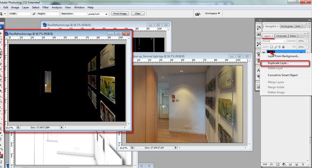
Go to the Layers tab and right-click on the Background layer. Choose Duplicate Layer from the list that pops up.
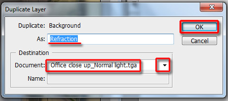
The Duplicate Layer dialog should appear. In the Destination group, choose Render.tga from its drop-down list. Rename it Refraction, as shown above, and click OK to close the dialog. The Refraction file should now appear as a new layer in the Render.tga document.
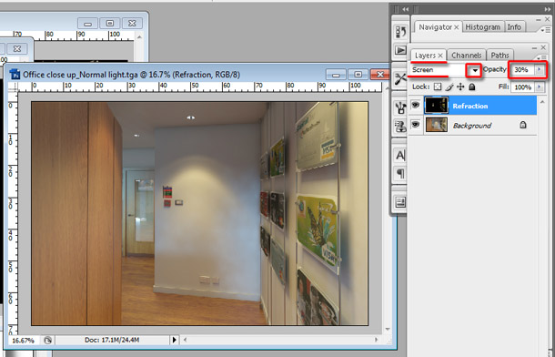
To blend the Refraction layer into the Background layer, browse through the list of blending modes available via the drop-down in the Layers palette. Screen worked best here, but feel free to try others if you like. Reduce the layer’s Opacity to about 30%.
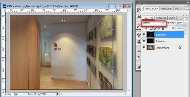
The next pass to add is the specular. Add Specular.tga as a new layer in the Render.tga document using the techniques as before, and rename it appropriately. Again, choose the Screen blending mode to integrate the layer into the composite.
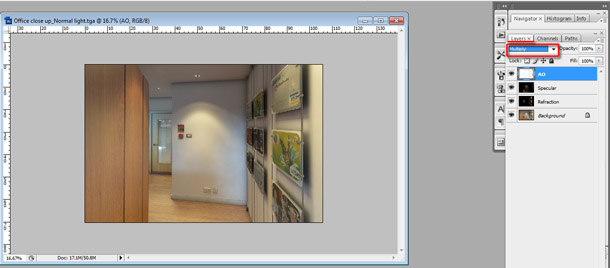
We will add the ambient occlusion element next. Add AO.tga as a new layer in Render.tga as before. This time, choose the Multiply blending mode.
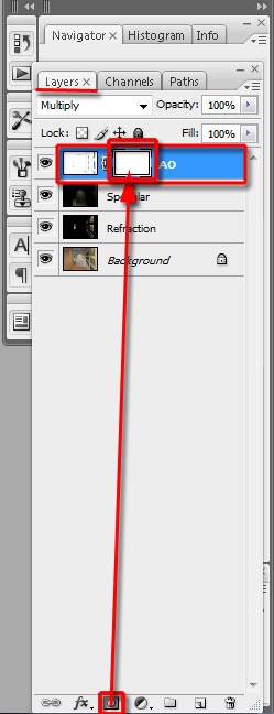
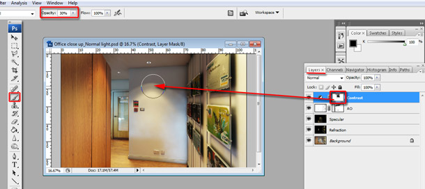
To fine-tune the image, we are going to reduce the contribution of the ambient occlusion layer to the composite in parts of the image where its effect is too strong. To do this, create a Layer Mask for the AO layer, by clicking on the icon shown in the image above.
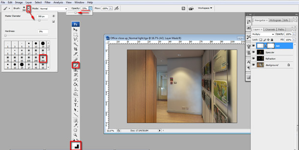
Select the Brush Tool [B]. Its options should appear on the main toolbar. Click on its icon to enable the brush parameters drop-down. Select a soft brush with a diameter of 300 pixels, as shown above. You can adjust the brush’s Hardness by dragging the slider.
Make sure the foreground and background colours (shown at the bottom of the main tool palette) are set to black and white. Painting on the mask layer in black will mask those parts of the image (that is, prevent the AO layer from contributing to the composite). Painting in white has the opposite effect. To switch between the two colours, press [X] on the keyboard. You can also reduce the Opacity of the brush by typing in the value required, or by dragging its slider in the toolbar. Reducing Opacity gives you more control over how pixels are masked.
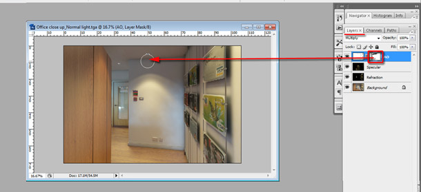
When you are satisfied, begin brushing away. As you do so, you can increase or decrease the brush diameter by pressing the square bracket keys on the keyboard. You can see the Layer Mask I created by opening Composite.psd from the download, but use your own judgement when painting your own mask layer.
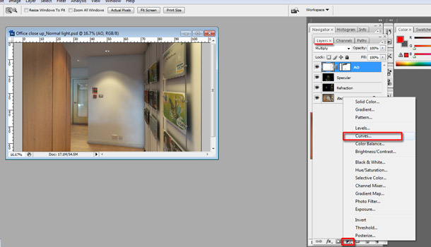
Next, we are going to add a bit of contrast to the image using a Curves Adjustment Layer. With the Layers tab selected, click the Create new fill or adjustment layer icon (ringed in the image above) and select Curves from the list that pops up.
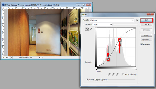
Its dialog should appear. The histogram represents the distribution of RGB values across the pixels in the image: the higher the histogram, the more pixels have that particular value. The graph that overlies the histogram controls the relationship between the RGB values of the raw image and those after the Curves adjustment has been applied.
We are going to add two new points to the graph to increase the contrast of the image. Click on the left-hand side of the graph in the position shown to create a new point, then move it down slightly to darken the shadow areas of the image. Click on the right-hand side of the graph and move the new point up to increase the brightness of the lighter areas.
You can preview the results on the image itself. When you’re happy with the changes, click OK to accept them.
Whenever you create a new Adjustment Layer, a layer mask is created automatically with it. This enables you to mask off parts of the image to prevent them from receiving the effect of the adjustment. To do this, click on the mask thumbnail in the Layers palette, and begin painting in the mask as you did with the AO layer, in order to fix any parts of the image that have become too bright.
Rename the Adjustment Layer as Contrast by right-clicking on it in the Layers palette and choosing Layer Properties from the menu that pops up.

Next, we are going to adjust the colour balance of specific parts of the image using the Curves adjustment once more. Create a new Curves Adjustment Layer. This time, instead of working on the RGB channel, we are going to be adjusting the Red and Blue channels individually.
Choose Red from the Channel drop-down. Moving the graph up makes the image redder; moving it down makes it more cyan. Which part of the graph you move determines whether the adjustment affects the pixels in the parts of the image that are already redder, or those that are already more cyan. Let’s add a touch of warmth to the image by making everything a little more red: click to add a new point in the middle of the curve, and move it up a little.
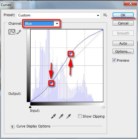
Next, choose the Blue channel from the drop-down. Moving the graph up makes the image bluer; moving it down makes it more yellow. Add a new point to the right-hand side of the graph, to affect the brighter parts of the image. Move it up to make the brighter areas bluer. Add a point on the left-hand side of the graph and move it down to make the darker areas yellower.
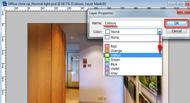
From the Layer Properties dialog, rename the layer Colours and choose Yellow from the Color drop-down. This changes the label colour of the layer in the Layers palette.
Choosing an appropriate name and label colour helps you see the function of the layer at a glance. This is especially important if you are going to pass the file on to another user who isn’t familiar with it.
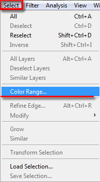
Next, we are going to tweak specific parts of the image. Let’s start with the metal pendants on the far right. Open your VrayWireColor or MultiMatteElement file. You can find Object_colours.tga in the download. Go to the top menu and choose Select > Color Range.
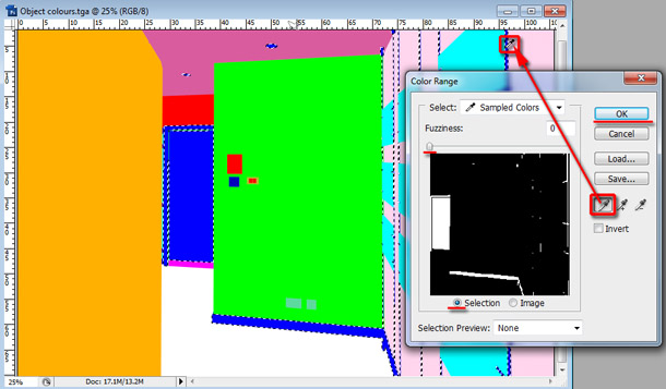
The Color Range dialog should pop up. Select the Eyedropper Tool (the icon without a plus or minus beneath it) and click on the part of the image corresponding to the pendants. The thumbnail shows the parts of the image you have selected. Use the Fuzziness slider to adjust the borders of these areas. When you are satisfied, click OK to close the dialog.
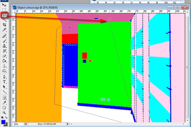
While it is still active, start to eliminate the unwanted parts of the selection (that is, anything that isn’t a pendant). Switch to the Polygonal Lasso Tool [L] and hold down [Alt] to begin subtracting from the selection. Click around the areas shown above. When you close the loop, they should be removed them from the selection.
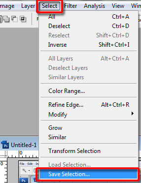
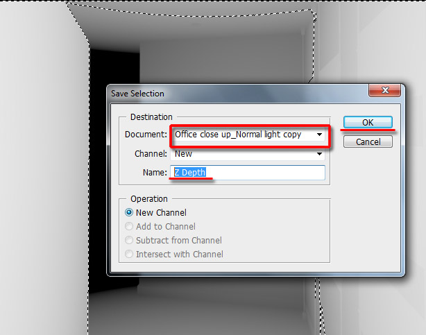
When you are satisfied, save the selection as a channel by choosing Select > Save Selection.
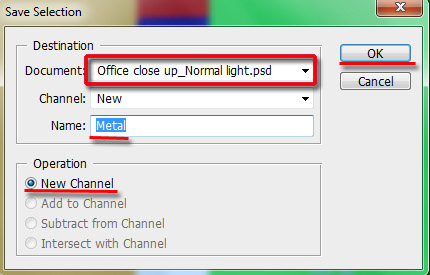
In the dialog that appears, choose Render.tga from the Document drop-down of the Destination group, and name the new channel Metal. Click OK to close the dialog.
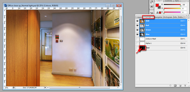
Switch back to the Render.tga document and switch to the Channels palette. [Ctrl]-click on the thumbnail next to the new Metal channel to enable the selection.
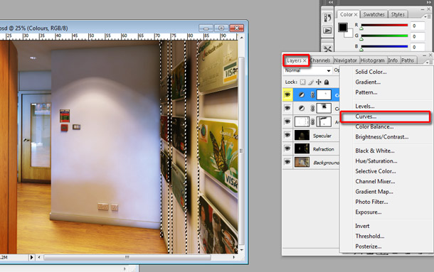
With the selection active, switch back to the Layers palette and add a Curves Adjustment Layer.
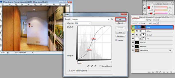
Use the same techniques as before to make the metal look darker and shinier. Rename the new layer as Metal and change its label colour to green.
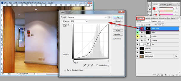
Use the same workflow to enhance the colour saturation and intensity of the reflections of the glass door at the back of the scene. Again, name your new layer appropriately.
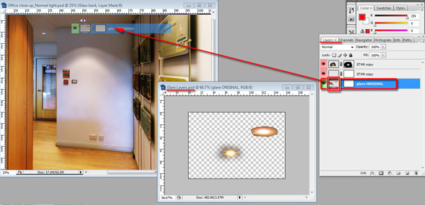
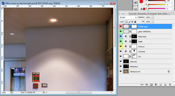
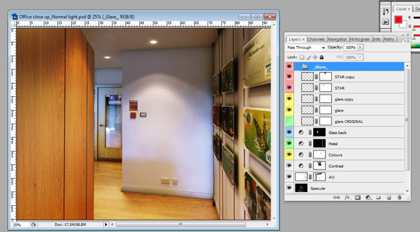
Now we will add a glare effect to the recessed lighting. Open Glare Layers.psd from the download. This contains glare and bloom effects extracted from a photo. You can find similar source material on Flickr or via a Google image search. The masks applied to each layer were created using the same workflow as before.
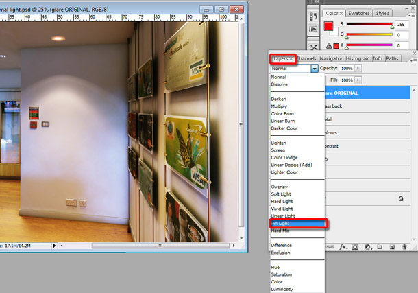
Start by dragging the glare ORIGINAL layer from the document into the main document. Make sure it is on top of all the layers you created earlier. If not, click and drag on the Layers palette to move it to the top of the stack. Position the glare over one of the lights in the image. Experiment with different blending modes from the drop-down in the Layers palette until you find one that works well: Pin Light worked best here.
Drag the STAR copy layer from Glare Layers.psd into the main document. Again, make sure it is positioned at the top of the layer stack. Set its blending mode to Screen. The overall glare effect should look much better now.
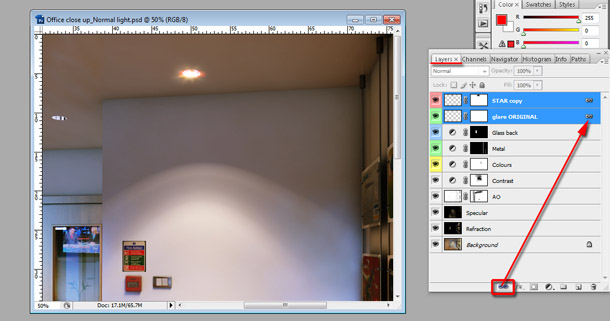
Next, we are going to link the two glare layers in order to copy them and move the duplicate over to the other recessed light. [Ctrl]-click in the Layers palette until both glare ORIGINAL and STAR copy are highlighted. Click the Link layers button at the foot of the palette.
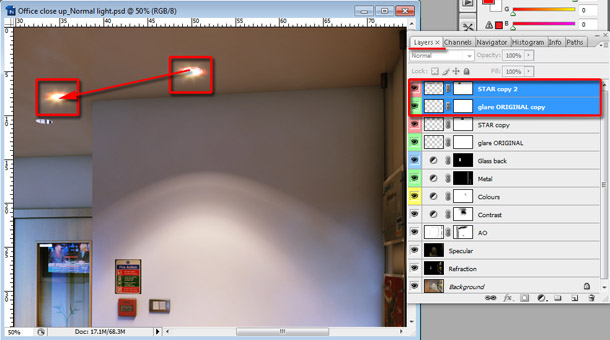
Switch to the Move Tool [V]. [Alt]-drag the glare over the other recessed light to create a duplicate. Link the two new layers.
The next task is to tweak the two new layers until the dimensions of the glare match that of the light. Hit [Ctrl]+[T] to enable the Free Transform Tool.
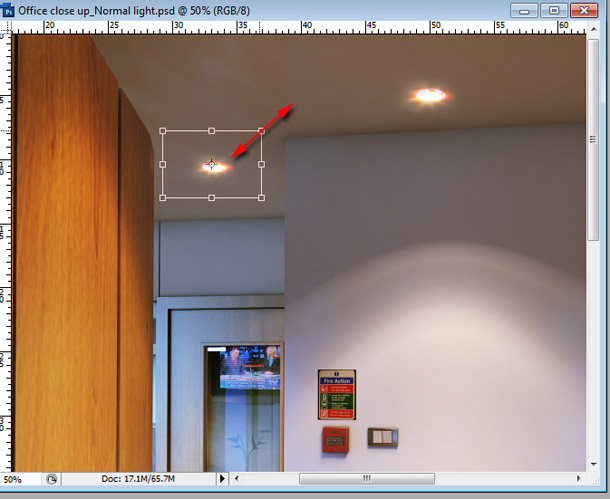
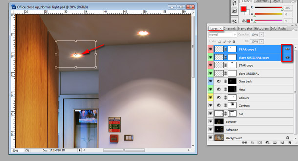
Move the control points around the glare until it is scaled and positioned correctly. To scale the glare proportionally (that is, so it retains a constant aspect ratio), hold [Shift] while dragging on a control point.
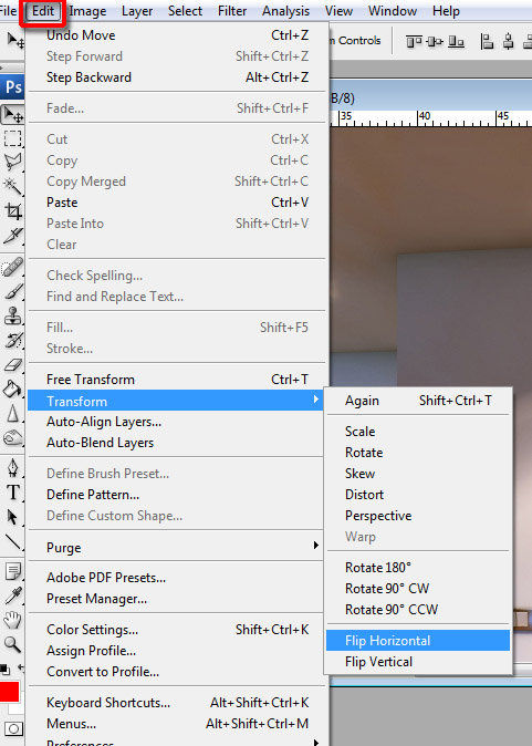
Select Edit > Transform > Flip Horizontal to flip the glare. This ensures the two glare effects don’t look unrealistically identical.
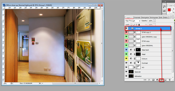
To tidy up the document, let’s create a Layer Group for all of the glare layers. Click the Create a new group icon at the foot of the Layers palette. Rename the new group Glare.
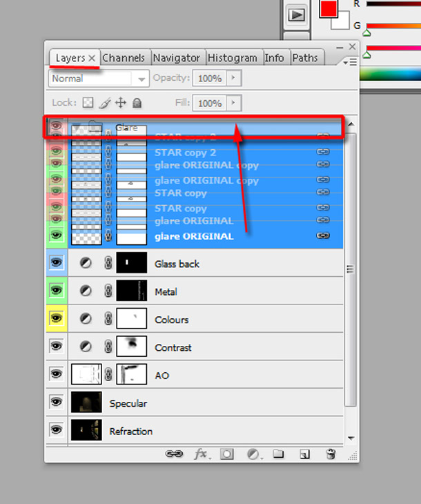
Working within the Layers palette, select and drag all of the relevant layers into the new group. To check that they are all safely inside, click on the arrow to the left of the folder icon to close the group.
Feel free to change names, label colours and positions of the layers to suit your workflow. Save your finished composite. You can see my final PSD file (Composite.psd) in the download.
The final step is to create effects like vignetting, depth of field and chromatic aberration. While some clients appreciate this, there are a number who don’t. For that reason, we are going to do this in a separate document.
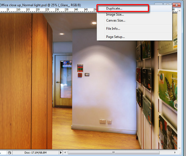
Right-click on the top corner of the document and choose to Duplicate it. (You may need to minimise the window and click on the top bar before this option appears.)
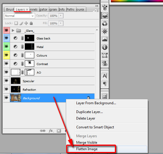
A duplicate document should be created. Right-click the Background layer in its Layers palette and choose Flatten Image.
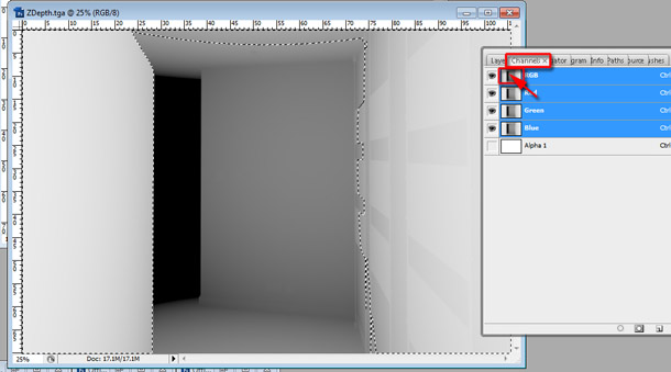
We are going to create the depth-of-field effect first. Open ZDepth.tga from the download. Switch to its Channels palette and [Ctrl]-click on the thumbnail for the RGB channel to activate the selection.
While the selection is still activate, save it to the duplicated document using the same workflow as before, naming the selection Z Depth.
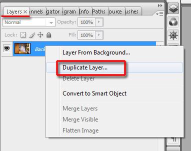
Back in the new document, duplicate the Background layer by right-clicking in the Layers palette and choosing Duplicate Layer.
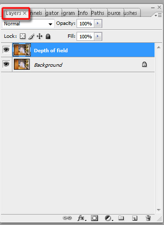
Rename the new layer Depth of field.
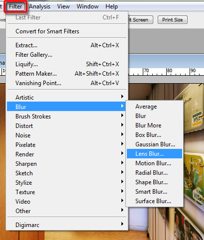
Select Filter > Blur > Lens Blur. Its dialog should appear.
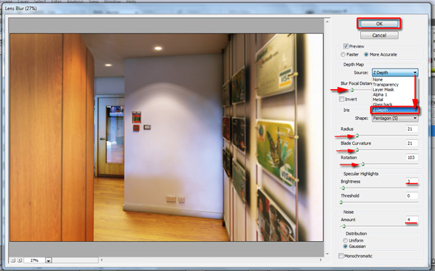
In the Depth Map group, select Z Depth from the Source drop-down to choose your Z Depth selection. In the Iris group, set Shape to Pentagon (5). Set the Blur Focal Distance to 37, Radius to 21, Blade Curvature to 21, Rotation to 103, Brightness to 3 and Noise Amount to 4. I found these parameter values worked well for this image, but feel free to experiment with other values if you like. Once you are satisfied, click OK.
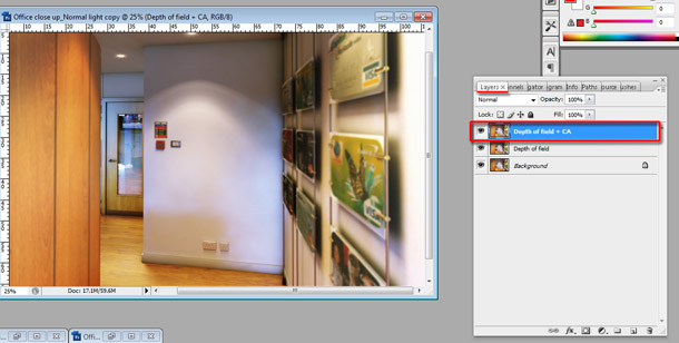
The final step is to add the chromatic aberration and vignetting effects. Duplicate the Depth of field layer and rename it Depth of field + CA.
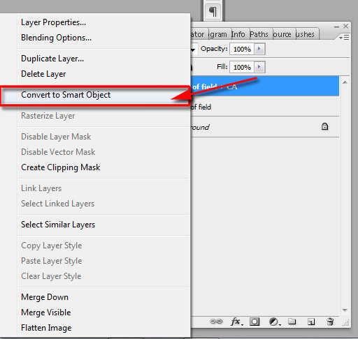
To give us more control over the effects, we are going to convert the layer into a Smart Object. This will enable use to edit it non-destructively. Right-click on it in the Layers palette and choose Convert to Smart Object. (Note: converting too many layers in your document to Smart Objects will increase memory usage and the size of your PSD file considerably.)
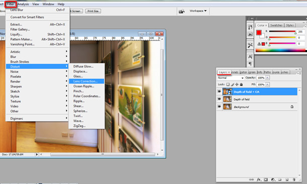
Select Filter > Distort > Lens Correction. Its dialog should appear.
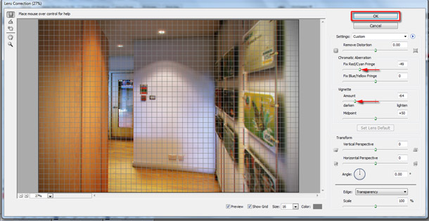
In the Chromatic Aberration group, set the Fix Red/Cyan Fringe value to -49. In the Vignette group, set Amount to -64 to darken the edges of the image. Again, feel free to choose different values if you think they work better. When you are happy, click OK to close the dialog.
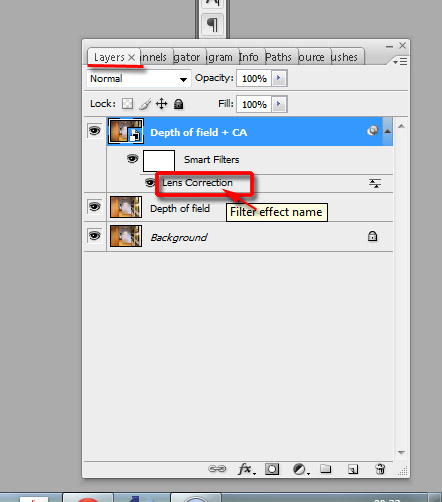
To edit any of the parameters, click on the Filter effect name in the Layers palette to re-open the dialog.
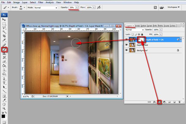
For more control over the chromatic aberration and vignetting, create a layer mask in the same way as you did before and brush into it to exclude parts of the image from the effect.
The post-production work is now complete. If you want to refer to my own Photoshop file, you can find it in the download as Depth_of_field.psd.
About the author
Jamie Cardoso is a senior computer artist who has been producing work for a wide range of clients worldwide since 1996. His work has been featured in 3D World magazine, 3DTotal and CGSociety.
He is the co-author of Realistic Architectural Visualization with 3ds Max and mental ray, and his most recent book, 3D Photorealistic Rendering: Interiors and Exteriors with V-Ray and 3ds Max, is available now.